Could a 1.15 DC-to-AC ratio be the exact point where your project's internal rate of return begins to diminish? In the 2026 regulatory environment, solar inverter sizing for commercial projects is no longer a simple capacity match; it's a high-stakes calculation of thermal resilience and regulatory compliance. You've likely seen how improper sizing leads to significant energy loss through clipping or unnecessary capital expenditure on oversized hardware. Balancing these variables requires an engineering mindset that prioritizes long-term system stability over short-term savings.
This guide delivers the precise technical framework required to optimize your inverter capacity, ensuring your system maintains peak performance in harsh climates while maximizing total energy yield. You'll master the strategies needed to navigate the NEC 2026 Section 110.16 arc flash marking requirements and satisfy the Physical Work Test for projects exceeding 1.5 MW AC. We'll examine how AI-powered energy management, non-FEOC sourcing strategies, and high-power string inverters minimize the Levelized Cost of Energy to secure the long-term viability of your commercial assets.
Key Takeaways
- Learn the technical framework for solar inverter sizing for commercial projects to transition from basic capacity matching to performance-based architecture.
- Master the calculation of Inverter Loading Ratios to mitigate power clipping while maximizing energy yield across the system's lifecycle.
- Identify the critical impact of thermal derating in high-temperature environments and implement advanced cooling strategies to protect nameplate capacity.
- Adopt a standardized engineering workflow that utilizes AI-assisted simulations to replace manual calculations for superior precision.
- Discover how Nippon Smart AI Inverters automate load management and thermal stress prevention to enhance long-term project ROI.
The Fundamentals of Solar Inverter Sizing for Commercial Systems
Commercial inverter sizing represents the strategic alignment of DC input energy with the AC output capacity of the power conversion hardware. In the 2026 energy landscape, this process has evolved from a simple capacity match into a complex, performance-based architecture. Engineers no longer aim for a basic 1:1 ratio. Instead, they design systems that leverage higher DC-to-AC ratios to ensure the inverter operates at its most efficient curve for the maximum number of hours per day. This precision is vital for large-scale assets where even a 1% variance in efficiency translates to significant revenue shifts over a twenty-five-year lifecycle. Mastering Solar inverter fundamentals allows developers to move beyond generic templates and create site-specific solutions that prioritize structural integrity and long-term yield.
Adopting a "Performance Architecture" mindset means you're balancing aggressive energy harvesting against the physical longevity of the equipment. It's a calculated trade-off. By pushing the DC loading, you increase production during low-light hours, but you must also manage the thermal stress that occurs during peak irradiance. This technical equilibrium is what defines a modern, bankable commercial solar project.
Why Sizing Dictates Commercial ROI
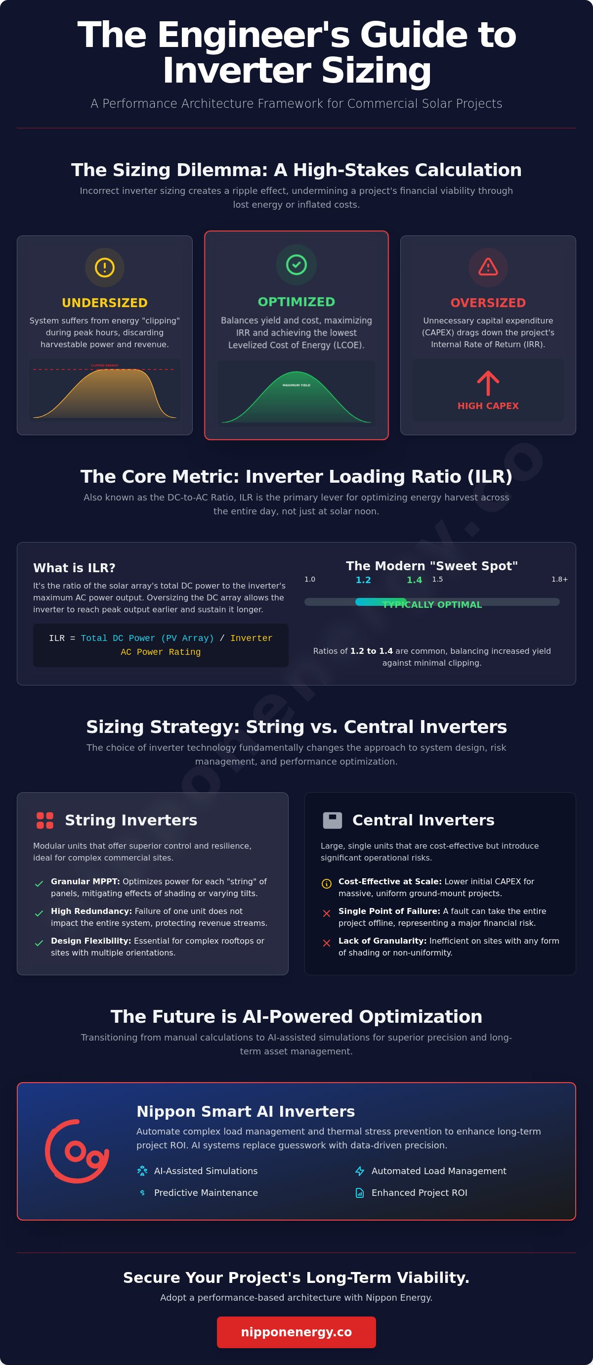
Incorrectly calculated capacity creates a ripple effect across the entire financial model of a project. When hardware is undersized, the system suffers from energy clipping during peak irradiance, which effectively throws away harvestable power. If the hardware is oversized, the initial capital expenditure (CAPEX) becomes unnecessarily high, dragging down the project's internal rate of return. Levelized Cost of Energy is the total cost of building and operating a generating plant over its financial life, divided by the total energy it produces. Achieving the lowest possible LCOE requires a sizing strategy that prevents accelerated component wear. Precise sizing ensures the inverter remains within its optimal thermal window, avoiding the premature failures that lead to costly mid-life replacements and unplanned downtime.
String vs. Central Inverter Sizing Considerations
The choice between modular string inverters and large-scale central blocks fundamentally changes how you approach solar inverter sizing for commercial projects. String inverters offer superior granularity; they allow for independent Maximum Power Point Tracking (MPPT) across different sections of an array. This flexibility is essential for complex commercial rooftops where shading or varying tilts are common. By utilizing modular designs, often seen in high-tier solar epc services, developers build inherent redundancy into the system. If one string inverter requires maintenance, the rest of the plant continues to produce power, protecting the owner's revenue stream. Central inverters, while cost-effective for massive, uniform ground-mount sites, lack this granular control. A single fault in a central unit can take the entire project offline, making the sizing of these large blocks a high-risk engineering decision.
Calculating the DC-to-AC Ratio: Balancing Clipping and Yield
The Inverter Loading Ratio (ILR), or the DC-to-AC ratio, represents the primary lever for optimizing solar inverter sizing for commercial projects. By calculating the ratio of the DC array's nameplate capacity to the inverter’s AC output, engineers determine how aggressively a system will harvest energy during non-peak hours. While a 1:1 ratio might seem intuitive, it's rarely optimal for commercial ROI. Modern designs typically favor an ILR between 1.2 and 1.4. This oversizing allows the system to reach its full AC capacity earlier in the morning and maintain it later into the afternoon, effectively widening the production curve. It's a calculated trade-off. While this results in "clipping" during the peak solar noon, the total daily energy yield often increases significantly, providing a superior financial outcome.
Finding the "sweet spot" requires a deep analysis of site-specific irradiance and utility rate structures. If the project's goal is to maximize energy during expensive peak-demand windows in the late afternoon, a more aggressive DC-to-AC ratio is often justified. This architectural decision ensures that the inverter remains fully loaded even as the sun's angle becomes less favorable. Data drives the decision. For those designing high-performance systems, evaluating the technical specifications of smart power conversion hardware is the first step toward achieving this balance.
The Mechanics of Inverter Clipping
Inverter clipping occurs when the DC power available from the array exceeds the maximum AC power the inverter can process. Instead of failing, the inverter manages this excess by shifting its operating point along the IV curve, increasing the voltage to reduce the current input. This process sheds potential energy to protect the internal components from overcurrent. You're effectively trading a small percentage of peak-hour production for a substantial gain in low-light performance. However, because 2026 HJT panels feature high efficiency and a better temperature coefficient, they require tighter sizing tolerances to avoid excessive thermal stress. You can find detailed guidance on managing these limits in this Thermal Derating Application Note, which outlines how hardware responds to high-load scenarios.
Oversizing vs. Undersizing: A Commercial Comparison
A "Safe Oversizing" strategy of 1.2 to 1.3 is often the baseline for standard monofacial modules. However, the introduction of Nippon TOPCon solar panels introduces bifacial gain into the equation. Bifaciality allows the rear side of the module to capture reflected light, potentially increasing the total DC energy by 5% to 20% without changing the front-side nameplate rating. If you apply an "Aggressive Oversizing" ratio of 1.5 or higher to a bifacial array, you risk excessive clipping that can lead to internal heat buildup. When evaluating solar inverter sizing for commercial projects, the 2026 engineering standard dictates that bifacial gain must be modeled as part of the total DC input to prevent the inverter from operating in a permanent state of thermal derating, which would otherwise compromise the system's longevity.
Accounting for Environmental Derating and Thermal Management
Environmental variables are not secondary considerations; they're foundational to solar inverter sizing for commercial projects. Thermal derating occurs when internal component temperatures exceed safe operating thresholds, forcing the power electronics to curtail output to prevent hardware damage. While a technical data sheet might list a 100kW AC capacity, this figure is typically rated at an ambient temperature of 25°C. In real-world commercial applications, particularly in the Middle East or South Asia, ambient temperatures frequently exceed 40°C. This heat triggers a significant reduction in realized performance, often dropping the actual output by 10% to 20% during the most productive hours of the day. Precise engineering requires calculating the "realized capacity" rather than relying on nominal nameplate values.
Cooling efficiency is further influenced by site-specific factors like altitude and humidity. Thinner air at higher elevations possesses a lower heat capacity, which means standard convection or forced-air cooling systems become less effective. In coastal or tropical industrial zones, high humidity can alter the thermal conductivity of the air and accelerate the oxidation of heat sinks. Ignoring these geographic variables leads to undersized thermal management systems that force the inverter into a permanent state of curtailed production. When designing for longevity, environmental factors are as critical as the raw wattage math used in the initial array layout.
Calculating Performance in High-Temperature Climates
Engineers must apply a specific derating curve provided by the manufacturer to understand how an inverter will behave under thermal load. If a unit features a derating slope starting at 40°C, a system operating in a 45°C environment will see its maximum power point limited by the thermal ceiling of its internal IGBTs. Inverter Thermal Management is the primary determinant of 25-year reliability in extreme environments. Selecting hardware with high-performance heat dissipation technology ensures that the system maintains its calculated DC-to-AC ratio without entering a protective shutdown or curtailment mode during peak summer irradiance.
Site-Specific Variables: Shading and Soiling
Partial shading from rooftop HVAC units or adjacent industrial structures disrupts the stability of the DC input, forcing MPPT trackers to constantly adjust to find the global maximum power point. This rapid switching generates additional internal heat and stresses the inverter’s capacitor banks. In heavy industrial zones, high soiling rates create non-uniform energy distribution across strings, which can lead to voltage mismatches. Establishing a rigorous protocol for solar system maintenance is essential to ensure that the sizing assumptions made during the design phase remain valid. Without consistent cleaning and inspection, the mismatch between the DC array and the AC inverter will grow, leading to avoidable energy losses and reduced system ROI.
A Professional Framework for Sizing Commercial Inverters
Modern engineering workflows for solar inverter sizing for commercial projects have transcended basic spreadsheet calculations. The 2026 industry standard dictates a transition toward AI-assisted simulations that model thousands of irradiance and thermal scenarios simultaneously. This methodical approach ensures that the selected hardware isn't just compatible, but optimized for the specific electrical environment of the facility. Future-proofing is now a core requirement; every sizing decision must account for the eventual integration of Nippon Lithium-ion Battery Storage Systems to manage peak demand and grid stability effectively.
Step 1: Define the AC Output and Grid Requirements
The sizing process begins at the point of interconnection. A facility's peak load and the utility’s specific interconnection limits define the absolute AC ceiling for the project. Identifying the correct voltage class, whether 400V, 480V, or medium voltage, serves as the primary filter for inverter selection. Engineers must also account for reactive power requirements and power factor correction to ensure the system supports grid stability without incurring utility penalties. This initial alignment prevents the costly mistake of selecting hardware that cannot legally or technically backfeed into the local distribution network.
Step 2: Optimize the DC-to-AC Ratio for Site Conditions
Once AC limits are established, the focus shifts to maximizing the DC-to-AC ratio based on site-specific irradiance data. Utilizing P50 and P90 probability models allows engineers to predict energy yield with high statistical confidence. The Inverter Loading Ratio is then fine-tuned by overlaying local temperature curves and bifacial gain factors discussed in previous sections. This step ensures that the string configuration remains within the inverter’s MPPT voltage window during both the coldest winter mornings and the hottest summer afternoons, preventing voltage-related shutdowns.
Step 3: Evaluate Harmonic Distortion and Power Quality
Power quality is a non-negotiable priority in industrial settings where sensitive electronics and heavy machinery coexist. Sized inverters must maintain Total Harmonic Distortion (THD) below 3% to prevent operational interference or damage to existing facility assets. High electromagnetic compatibility (EMC) ensures that the power conversion process doesn't disrupt local communication networks or control systems. For projects requiring this level of technical precision, partnering with Nippon Energy for project development ensures your system architecture meets these rigorous 2026 engineering standards.
Integrating Smart AI Inverters into Commercial Project Architecture
The engineering frameworks established in previous sections provide the necessary blueprint for success; however, the hardware must be capable of executing these complex calculations in real-time. Nippon Smart AI Inverters represent the logical conclusion of precise solar inverter sizing for commercial projects. While traditional hardware operates on static parameters, AI-integrated systems adapt to the fluid dynamics of an industrial environment. This shift from reactive to proactive management ensures that the system doesn't just meet its design targets but consistently exceeds them by optimizing the conversion process at the edge of the network. Precision in hardware selection is what transforms a theoretical model into a high-yielding physical asset.
The Role of AI in Dynamic Sizing and Load Management
AI algorithms now play a critical role in mitigating the minor sizing errors that occur due to unpredictable weather patterns or rapid degradation. By optimizing Maximum Power Point Tracking (MPPT) at millisecond intervals, these inverters capture energy that traditional units would lose to clipping or voltage lag. Predictive cooling is perhaps the most significant advancement for high-temperature climates. The AI anticipates thermal peaks by analyzing historical irradiance data and local forecasts, activating advanced cooling protocols before the internal components reach a derating threshold. This proactive thermal management preserves the system’s realized capacity during the hottest hours of operation. For a deeper look at these advancements, review the strategic benefits of AI in solar energy for long-term asset monitoring.
Future-Proofing with NipponHev Integrated Systems
Achieving maximum accuracy in solar inverter sizing for commercial projects is most effective within a single-manufacturer ecosystem. The NipponHev approach integrates Nippon HJT solar panels with Smart AI Inverters to create a seamless energy architecture. Because these components are engineered to work in tandem, the communication between the DC generation and AC conversion layers is instantaneous. This synergy allows for a more aggressive DC-to-AC ratio because the system can manage the resulting thermal and electrical loads with surgical precision. It eliminates the "safety buffers" often required when mixing disparate brands, which typically lead to under-performance and increased LCOE.
Investing in a unified system architecture ensures that your commercial asset remains resilient against the evolving demands of the 2026 grid. We invite stakeholders and lead engineers to schedule a technical review of their current project designs to ensure every kilowatt is accounted for. For more information on creating a unified energy footprint, explore our NipponHev System consultation options to ensure your project’s sizing is backed by world-class engineering and visionary technology.
Engineering the Future of Commercial Energy
Mastering the technical nuances of solar inverter sizing for commercial projects ensures that your asset remains resilient against the thermal and regulatory challenges of the 2026 energy landscape. By aligning high-efficiency HJT and TOPCon technologies with precise DC-to-AC ratios, you secure maximum energy yield while minimizing the Levelized Cost of Energy over a twenty-five-year lifecycle. Our proprietary Nippon Smart AI Inverters achieve a 99% MPPT efficiency, providing the technical precision required to mitigate clipping and manage dynamic loads automatically. With a global EPC presence across the Middle East, Asia, and Europe, Nippon Energy provides the architectural expertise to transform complex engineering requirements into monumental performance.
We invite you to Request a Professional Engineering Consultation for Your Commercial Solar Project today. Building a reliable, high-performance energy infrastructure starts with a commitment to technical excellence; we're ready to partner with you for large-scale success. Let's build a more powerful future together.
Frequently Asked Questions
What is the ideal DC-to-AC ratio for commercial solar in 2026?
The ideal DC-to-AC ratio for most commercial projects typically ranges between 1.2 and 1.4. This loading ratio allows for a wider daily production curve by enabling the inverter to reach its full AC capacity earlier in the morning and maintain it later into the evening. While this results in some peak-hour clipping, the total energy yield is maximized, providing a superior return on investment for the project owner.
How does high ambient temperature affect solar inverter sizing?
High ambient temperatures trigger thermal derating, which reduces the inverter’s maximum power output to protect sensitive internal electronics. Most commercial units are rated at 25°C; however, in regions where temperatures exceed 45°C, realized capacity can drop by 20% or more. Accurate solar inverter sizing for commercial projects must account for these site-specific derating curves to prevent unplanned energy shortfalls during peak irradiance periods.
Can I use a residential inverter for a small commercial project?
It's not recommended to use residential inverters for commercial applications due to fundamental differences in electrical architecture and durability. Commercial projects typically require three-phase power and must comply with industrial grid standards like UL 1741 SB. Residential units lack the advanced thermal management and communication protocols necessary to handle the higher duty cycles and complex load profiles found in industrial environments.
What is inverter clipping and how much energy loss is acceptable?
Inverter clipping is the shedding of excess DC energy when the array output exceeds the inverter’s maximum AC capacity. An acceptable energy loss due to clipping is generally between 1% and 3% of the total annual yield. If losses exceed this threshold, the system is likely suffering from excessive oversizing, which can lead to unnecessary thermal stress and reduced longevity for the power conversion hardware.
How do bifacial solar panels impact inverter sizing calculations?
Bifacial solar panels increase the effective DC input by 5% to 20% due to rear-side light capture, requiring a more conservative loading ratio. When calculating solar inverter sizing for commercial projects using bifacial modules, engineers must treat the rear-side gain as part of the total DC nameplate. Failure to account for this extra energy can lead to severe clipping and accelerated component wear during high-albedo conditions.
What happens if I undersize my commercial solar inverter?
Undersizing a commercial inverter leads to excessive power clipping and forces the hardware to operate at its thermal limit for extended periods. This constant high-load state accelerates the degradation of capacitors and IGBTs, significantly shortening the system's lifespan. While it might reduce initial capital expenditure, the resulting energy loss and premature replacement costs will negatively impact the project's long-term LCOE and financial stability.
Why is MPPT voltage range critical for string inverter sizing?
The MPPT voltage range is critical because it defines the window in which the inverter tracks and converts energy at peak efficiency. If the string voltage falls below the minimum threshold on hot days or exceeds the maximum on cold mornings, the inverter will shut down or operate inefficiently. Precise string sizing ensures the DC input remains within this optimal window across all seasonal temperature variations.
How does AI technology improve inverter sizing efficiency?
AI technology improves sizing efficiency by utilizing predictive algorithms to manage thermal loads and optimize MPPT in real-time. Smart systems analyze historical weather patterns to anticipate irradiance peaks, allowing the inverter to adjust its cooling protocols proactively. This dynamic management reduces the need for large safety buffers in the design phase, allowing for more aggressive loading without compromising the integrity of the hardware.


